Beam elements in ABAQUS make me a little confused, especially about the shear stiffness and elements for open sections. In this post, I want to make a summary of the elements in ABAQUS and give an example about the settings of beam elements.
Beam element library
Beam elements in a plane only have active degrees of freedom 1, 2, 6. Beam elements in space have active degrees of freedom 1, 2, 3, 4, 5, 6. Open section beams in space B31OS, B31OSH, B32OS, B32OSH have active degrees of freedom 1, 2, 3, 4, 5, 6, 7. The beam elements in ABAQUS Standard and Explicit (v6.14) are summarized below.
Beam elements in ABAQUS Standard
| B21 | 2-node linear beam in a plane (Section 29.3.8) |
| B21H | 2-node linear beam in a plane, hybrid formulation (Section 29.3.8) |
| B22 | 3-node quadratic beam in a plane (Section 29.3.8) |
| B22H | 3-node quadratic beam in a plane, hybrid formulation (Section 29.3.8) |
| B23 | 2-node cubic beam in a plane (Section 29.3.8) |
| B23H | 2-node cubic beam in a plane, hybrid formulation (Section 29.3.8) |
| B31 | 2-node linear beam in space (Section 29.3.8) |
| B31H | 2-node linear beam in space, hybrid formulation (Section 29.3.8) |
| B31OS | 2-node linear open-section beam in space (Section 29.3.8) |
| B31OSH | 2-node linear open-section beam in space, hybrid formulation (Section 29.3.8) |
| B32 | 3-node quadratic beam in space (Section 29.3.8) |
| B32H | 3-node quadratic beam in space, hybrid formulation (Section 29.3.8) |
| B32OS | 3-node quadratic open-section beam in space (Section 29.3.8) |
| B32OSH | 3-node quadratic open-section beam in space, hybrid formulation (Section 29.3.8) |
| B33 | 2-node cubic beam in space (Section 29.3.8) |
| B33H | 2-node cubic beam in space, hybrid formulation (Section 29.3.8) |
| PIPE21 | 2-node linear pipe in a plane (Section 29.3.8) |
| PIPE21H | 2-node linear pipe in a plane, hybrid formulation (Section 29.3.8) |
| PIPE22 | 3-node quadratic pipe in a plane (Section 29.3.8) |
| PIPE22H | 3-node quadratic pipe in a plane, hybrid formulation (Section 29.3.8) |
| PIPE31 | 2-node linear pipe in space (Section 29.3.8) |
| PIPE31H | 2-node linear pipe in space, hybrid formulation (Section 29.3.8) |
| PIPE32 | 3-node quadratic pipe in space (Section 29.3.8) |
| PIPE32H | 3-node quadratic pipe in space, hybrid formulation (Section 29.3.8) |
Beam elements in ABAQUS Explicit
| B21 | 2-node linear beam in a plane (Section 29.3.8) |
| B22 | 3-node quadratic beam in a plane (Section 29.3.8) |
| B31 | 2-node linear beam in space (Section 29.3.8) |
| B32 | 3-node quadratic beam in space (Section 29.3.8) |
| PIPE21 | 2-node linear pipe in a plane (Section 29.3.8) |
| PIPE31 | 2-node linear pipe in space (Section 29.3.8) |
Euler-Bernoulli (slender) beams
Euler-Bernoulli beams (B23, B23H, B33, and B33H) are available only in Abaqus/Standard. These elements do not allow for transverse shear deformation; plane sections initially normal to the beam’s axis remain plane (if there is no warping) and normal to the beam axis. They should be used only to model slender beams: the beam’s cross-sectional dimensions should be small compared to typical distances along its axis (such as the distance between support points or the wavelength of the highest mode that participates in a dynamic response). For beams made of uniform material, typical dimensions in the cross-section should be less than about 1/15 of typical axial distances for transverse shear flexibility to be negligible.
Timoshenko (shear flexible) beams
Timoshenko beams (B21, B22, B31, B31OS, B32, B32OS, PIPE21, PIPE22, PIPE31, PIPE32, and their “hybrid” equivalents) allow for transverse shear deformation. They can be used for thick (“stout”) as well as slender beams. For beams made from uniform material, shear flexible beam theory can provide useful results for cross-sectional dimensions up to 1/8 of typical axial distances or the wavelength of the highest natural mode that contributes significantly to the response. Beyond this ratio the approximations that allow the member’s behavior to be described solely as a function of axial position no longer provide adequate accuracy.
Abaqus assumes that the transverse shear behavior of Timoshenko beams is linear elastic with a fixed modulus and, thus, independent of the response of the beam section to axial stretch and bending.
For most beam sections, Abaqus will calculate the transverse shear stiffness values required in the element formulation. You can override these default values as described below in “Defining the transverse shear stiffness and the slenderness compensation factor.” The default shear stiffness values are not calculated in some cases if estimates of shear moduli are unavailable during the preprocessing stage of input; for example, when the material behavior is defined by user subroutine UMAT, UHYPEL, UHYPER, or VUMAT. In such cases you must define the transverse shear stiffness.
The Timoshenko beams can be subjected to large axial strains. The axial strains due to torsion are assumed to be small. In combined axial-torsion loading, torsional shear strains are calculated accurately only when the axial strain is not large.
Node ordering on elements
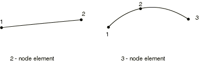
For beams in space an additional node may be given after a beam element’s connectivity (in the element definition—see “Element definition,” Section 2.2.1) to define the approximate direction of the first cross-section axis, n1. See “Beam element cross-section orientation,” Section 29.3.4, for details.
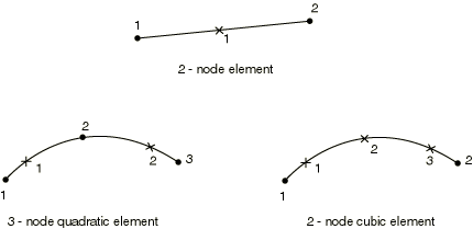
Numbering of integration points for output
Choosing the beam elements
- In the simulation with contacts, the first-order beam element including shear effects B21 and B31 are preferred.
- When the transverse shear effects are not ignorable, the Timoshenko beam elements should be used.
- When the structure has either very large or very small stiffness, the hybrid beam elements (B31H, B32H etc.) should be adopted in the analysis with geometrical nonlinearity.
- The third-order Euler-Bernoulli beam elements (B23, B33) have high precision for the simulation of beams with distributed loads, such as the dynamic vibration analysis.
Stress and other tensors (including strain tensors) are available for elements with displacement degrees of freedom. All tensors, except for meshed sections, have the same components. For example, the stress components are as follows:
| S11 | Axial stress. |
| S22 | Hoop stress (available only for pipe elements). |
| S33 | Radial stress (available only for thick-walled pipe elements). |
| S12 | Shear stress caused by torsion (available only for beam-type elements in space). This component is not available when thin-walled, open sections are employed (I-section, L-section, and arbitrary open section). |
Stress and strain for section points for meshed sections
| S11 | Axial stress. |
| S12 | Shear stress along the second cross-section axis caused by shear force and, for beam elements in space, torsion. |
| S13 | Shear stress along the first cross-section axis caused by shear force and torsion (available only for beams in space). |
Section forces, moments, and transverse shear forces
| SF1 | Axial force. |
| SF2 | Transverse shear force in the local 2-direction (not available for B23, B23H, B33, B33H). |
| SF3 | Transverse shear force in the local 1-direction (available only for beams in space, not available for B33, B33H). |
| SM1 | Bending moment about the local 1-axis. |
| SM2 | Bending moment about the local 2-axis (available only for beams in space). |
| SM3 | Twisting moment about the beam axis (available only for beams in space). |
| BIMOM | Bimoment due to warping (available only for open-section beams in space). |
| ESF1 | Effective axial force for beams subjected to pressure loading (available for all Abaqus/Standard stress/displacement analysis types except response spectrum and random response). |
Section strains, curvatures, and transverse shear strains
| SE1 | Axial strain. |
| SE2 | Transverse shear strain in the local 2-direction (not available for B23, B23H, B33, and B33H). |
| SE3 | Transverse shear strain in the local 1-direction (available only for beams in space, not available for B33 and B33H). |
| SK1 | Curvature change about the local 1-axis. |
| SK2 | Curvature change about the local 2-axis (available only for beams in space). |
| SK3 | Twist of the beam (available only for beams in space). |
| BICURV | Bicurvature due to warping (available only for open-section beams in space). |
Beam cross section library
The Abaqus beam cross-section library contains solid sections (circular, rectangular, and trapezoidal), closed thin-walled sections (box, hexagonal, and pipe), open thin-walled sections (I-shaped, T-shaped, or L-shaped), and a thick-walled pipe section. Abaqus also provides an arbitrary thin-walled section definition; Abaqus will treat this section type as a closed or open section, depending on how the section is defined.
Trapezoidal, I, and arbitrary library sections allow you to define the location of the origin of the local coordinate system. Other section types—such as rectangular, circular, L, or pipe—have preset origins.
Generalized cross section
You can specify “generalized” cross-sections by specifying the geometric quantities necessary to define the section. Such generalized sections can be used only with linear material behavior although the section response can be linear or nonlinear. Nonlinear generalized cross-sections are not supported in ABAQUS/CAE.
*Beam General Section, section=GENERAL
*Beam General Section, section=NONLINEAR GENERAL
A general beam section:
- is used to define beam section properties that are computed once and held constant for the entire analysis;
- can be used to define linear or nonlinear section behavior;
- for linear section behavior can be associated only with linear material behavior
- enables the use of meshed cross-sections (“Meshed beam cross-sections,” Section 10.6.1);
- enables the use of tapered cross-sections (Abaqus/Standard only).
In ABAQUS/CAE, you can define a beam section with generalized shape shown as below. The section geometry properties can be defined in this dialog window. The location of the centroid and shear center, the output points as well as the transverse shear stiffness are allowed to define directly as figured below. The keywords generated in input file are listed below.
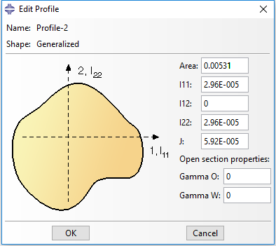
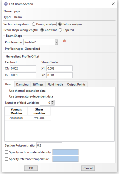
** Section: pipe Profile: Profile-2

*Beam General Section, elset=_PickedSet2, poisson = 0.2, section=GENERAL
0.00531, 2.96e-05, 0., 2.96e-05, 5.92e-05
0.,0.,-1.
2e+08, 7.69231e+07

*Shear Center
0.002, 0.001

*Centroid
0.002, 0.001

*Section Points
0.002, 0.001, 0.001, 0.

*Transverse Shear
6.9591e+06, 6.9591e+06, 0.2
The Section Poisson value must be between -1.0 and 0.5 with a default value set to 0.0 so that this effect is ignored. This value is only valid for the shear flexible elements providing for a possible uniform cross-sectional area change. This effect is considered only in geometrically nonlinear analysis (see “Defining an analysis,” Section 6.1.2) and is provided to model the reduction or increase in the cross-sectional area for a beam subjected to large axial stretch. Setting the effective Poisson’s ratio to 0.5 implies that the overall response of the section is incompressible. This behavior is appropriate if the beam is made of rubber or if it is made of a typical metal whose overall response at large deformation is essentially incompressible (because it is dominated by plasticity). Values between 0.0 and 0.5 mean that the cross-sectional area changes proportionally between no change and incompressibility, respectively. A negative value of the effective Poisson’s ratio will result in an increase in the cross-sectional area in response to tensile axial strains. Why the cross section area increases under tensile axial strain?
If you want to get the stress and strain on integration points, you have to define the output points in “Edit Beam Section”. To locate points in the section at which output of axial strain (and, for linear section behavior, axial stress) is required, specify the local \(\left( {{x_1},{x_2}} \right)\) coordinates of the point in the cross-section: Abaqus numbers the points 1, 2, … in the order that they are given.
The variation of \(\varepsilon \) over the section is given by
\[\varepsilon = {\varepsilon _c} + {\kappa _1}\left( {{x_2} – {x_{2c}}} \right) – {\kappa _2}\left( {{x_1} – {x_{1c}}} \right)\]
where \(\left( {{x_{1c}},{x_{2c}}} \right)\) are the local coordinates of the centroid of the beam section and \({\kappa _1}\) and \({\kappa _2}\) are the changes of curvature for the section.
Meshed cross section
The response of some structures is beam-like, yet the beam cross-section geometry or multi-material makeup of the cross-section do not permit the use of a predefined library beam cross-section. In these cases a meshed cross-section can be used to model the beam cross-section and to generate beam cross-section properties appropriate for subsequent use in a Timoshenko beam analysis. The beam properties are generated assuming a thick-walled (solid) cross-section with unconstrained out-of-plane warping, so open-section beam elements cannot use the beam cross-section properties generated from the meshed section. The generated beam cross-section properties include axial, bending, torsional, and transverse shear stiffnesses; mass, rotary inertia, and damping properties; and the centroid and shear center of the cross-section. In addition, the equivalent beam cross-section properties include information on stress recovery, such as the warping function and its derivatives.
Meshed cross-sections:
- allow for the description of a beam cross-section including multiple materials and complex geometry;
- are meshed in Abaqus/Standard with two-dimensional warping elements, which have an out-of-plane warping displacement as the only degree of freedom;
- generate beam cross-section properties that can be used in a subsequent beam element analysis in either Abaqus/Standard or Abaqus/Explicit;
- allow only isotropic linear elastic material behavior or orthotropic linear elastic material behavior for warping elements;
- allow stress and strain postprocessing on the beam element model or the two-dimensional warping element model.
The procedure for analyzing and postprocessing a beam analysis using a meshed cross-section is as follows:
- Mesh and analyze a two-dimensional Abaqus/Standard model of the beam cross-section.
- Use the generated cross-sectional properties in an Abaqus/Standard or Abaqus/Explicit beam analysis.
- Using the beam analysis results, postprocess from the beam model or the two-dimensional cross-section model.
The cross-section is meshed using special-purpose two-dimensional elements: WARP2D3 (3-node triangular) and WARP2D4 (4-node quadrilateral). These elements have one degree of freedom per node representing the value of the out-of-plane warping function and use a solid section definition. The way to generate and use the generated cross section properties is detailed in Abaqus Analysis User’s Guide.
Keywords edition
The keywords in input files for general section and meshed cross section can be referred to Abaqus Keywords Reference Guide and summarized here.
*Beam General Section, elset=elset_name, section=GENERAL
A, \({I_{11}}\), \({I_{12}}\), \({I_{22}}\), J, \({\Gamma _0}\), \({\Gamma _W}\)
0, 0, -1 (optional)
E, G*Beam General Section, elset=elset_name, section=NONLINEAR GENERAL
A, \({I_{11}}\), \({I_{12}}\), \({I_{22}}\), J, \({\Gamma _0}\), \({\Gamma _W}\)
0, 0, -1 (optional)
E, G
The axial and bending behaviors of the section are defined by using the *AXIAL, *M1, *M2, *TORQUE, and *THERMAL EXPANSION options.*Beam General Section, elset=elset_name, section=MESHED
0, 0, -1
(EA), \({\left( {EI} \right)_{11}}\), \({\left( {EI} \right)_{12}}\), \({\left( {EI} \right)_{22}}\), (GJ)
\(\rho A\), \({\left( {\rho I} \right)_{11}}\), \({\left( {\rho I} \right)_{12}}\), \({\left( {\rho I} \right)_{22}}\), \({x_{1cm}}\), \({x_{2cm}}\)
Notes: (1) Sectorial moment \({\Gamma _0}\) and warping constant \({\Gamma _W}\) are only needed in ABAQUS/Standard when the section is associated with open=section beam elements. (2) (0, 0, -1) are the default values for beam orientation if the first beam section axis is not defined by an additional node in the element’s connectivity. (3) If the TAPER parameter is included, two lines of properties of node A and node B are required. (4) \({x_{1cm}}\) and \({x_{2cm}}\) are the local 1-coordinate and 2-coordinate of the center of mass.
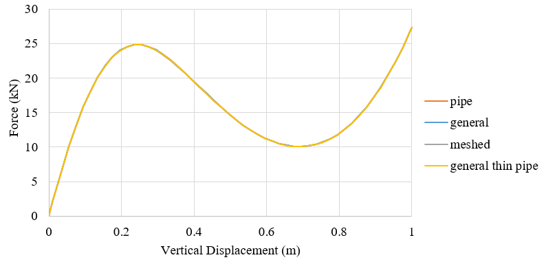
Example of different section settings
A steel frame with pipe section is analyzed with different section settings with beam element B31. Displacement control method with a maximum vertical displacement 1m at the vertex of the frame is adopted. The pipe section has a diameter of 219.1mm and thickness of 8mm. The material possesses density of 77 and elastic module of 200GPa and the poison ratio of 0.3.
The transverse shear stiffness are specified. The keywords in input file are listed below.
*Beam Section, elset=_PickedSet2, material=pipe, section=THICK PIPE
0.10955, 0.008
0.,0.,-1.
*Transverse Shear
204059, 204059,
*Beam General Section, elset=_PickedSet2, section=GENERAL
0.00531, 2.96e-05, 0., 2.96e-05, 5.92e-05
0.,0.,-1.
2e+08, 7.69231e+07
*Transverse Shear
204059, 204059,
*Beam General Section, elset=_PickedSet2,section=MESHED
0.,0.,-1.
1.06E+06,5.92E+03,0.00E+00,5.92E+03,4.55E+03
8.18E+07 ,4.56E+05,0.00E+00,4.56E+05,0,0

*Transverse Shear
204059,204059,0
*Beam General Section, elset=_PickedSet2, section=PIPE
0.10955, 0.008
0.,0.,-1.
2e+08, 7.69231e+07

*Transverse Shear
204059, 204059,
The force-displacement curves of the vertex are illustrated in the following figure and accord well with each other.
Notes:
- The choice of section integration for generalized section beam can only be “Before analysis”.
- only thin-walled pipe section can be used in general section with keywords in input file.
6 comments On Beam elements in ABAQUS
Thank you for another fantastic article. Where else could anybody get that type of information in such an ideal way of writing? I have a presentation next week, and I’m on the look for such information.
Hi Dorothy,
thank you very much for this article!
Kind regards
Jannik
Hello,
Thank you so much for this, But I would like you to know that some of the image links in this article are broken and are no longer active?
Could this be remedied, or the images replaced?
Thank you,
Alhasan
Hi Alhasan,
Thank you so much. The images work now.
Best,
Dorothy
Thank you so much. 🙂
Hi Dorothy,
Thank you for this amazing explanation!