I analyzed a specimen of ductile material with explicit dynamic method about one year ago. Recently, I want to review the model and summarize the process of analysis.
Stress and strain of material in ABAQUS
Stress and strain in the definition of material in abauqs should be converted to true stress \(\sigma\) and true plastic strain \({\varepsilon _p}\) from the data obtained in experiments. The stress and strain achieved in experiments are engineering stress \({\sigma _{{\rm{eng}}}}\) and engineering strain \({{\varepsilon _{{\rm{eng}}}}}\), respectively.
Considering the incompressibility of plastic material, which means constant volume, we get
\[{l_0}{A_0} = lA\]
in which, \({l_0}\) and \({A_0}\) are initial length and initial area, \({l}\) and \({A}\) are current length and current area. Thus, real stress \(\sigma \) can be derived as
\[\sigma = \frac{F}{A} = \frac{F}{{{A_0}}}\frac{l}{{{l_0}}} = {\sigma _{{\rm{eng}}}}\frac{l}{{{l_0}}} = {\sigma _{{\rm{nom}}}}\left( {1 + {\varepsilon _{{\rm{eng}}}}} \right)\]
Engineering strain \({{\varepsilon _{{\rm{eng}}}}}\) can be written as
\[{\varepsilon _{{\rm{eng}}}} = \frac{{l – {l_0}}}{{{l_0}}} = \frac{l}{{{l_0}}} – 1\]
Thus, the relation between real stress, real strain and engineering strain is given as
\[\sigma = {\sigma _{{\rm{eng}}}}\left( {1 + {\varepsilon _{{\rm{eng}}}}} \right)\]
\[\varepsilon = \ln \left( {1 + {\varepsilon _{{\rm{eng}}}}} \right)\]
Plastic strain can be obtained by subtracting the elastic part from total strain,
\[{\varepsilon _p} = \varepsilon – {\varepsilon _e} = \varepsilon – \sigma /E\]
Damage and failure for ductile metal
#1. Damage initiation
The material damage initiation capability for ductile metals is intended as a general capability for predicting initiation of damage in metals, including ductile, shear and other criteria. Ductile criterion is used to predict the onset of damage in material, assuming the equivalent plastic strain is a function of stress triaxiality and strain rate.
To simulate the fracture of a coupon, the fracture stress and fracture strain should be calculated with a similar method as true stress and strain.
\[{\sigma _f} = {F_f}/{A_f}\]
\[{\varepsilon _f} = \ln \left( {{A_0}/{A_f}} \right)\]
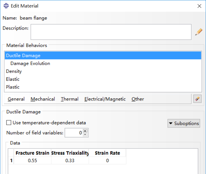
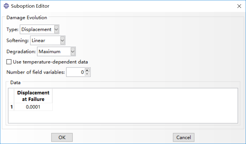
As concluded in [1], fracture strain is critical to fracture of coupon, while stress triaxiality and strain rate has little influence. Displacement at failure (will be discussed below) has certain impact on fracture and results with small values are consistent. In this analysis, values in [1] are adopted, shown in the following figures.

#2. Damage evolution for ductile metals
Damage evolution capability for ductile metals assumes that damage is characterized by the progressive degradation of the material stiffness, leading to material failure. It also takes into account the combined effect of different damage mechanisms acting simultaneously on the same material and includes options to specify how each mechanism contributes to the overall material degradation. Two types of damage evolution methods are available in abaqus, displacement type (based on effective plastic displacement) and energy type (based on energy dissipated during the damage process).
Displacement type is adopted in damage evolution. Once the damage initiation criterion has been reached, the effective plastic displacement can be defined with the characteristic length of the element. Instantaneous failure will occur if the plastic displacement at failure is specified as 0, which is not recommended by abaqus because it causes a sudden drop of the stress at material point that can lead to dynamic instabilities. The linear damage evolution law defines a truly linear stress-strain softening response only if the effective response of the material is perfectly plastic (constant yield stress) after damage initiation. For mare details, one can refer to Abaqus Analysis User’s Guide.

# 3. Element removal from mesh
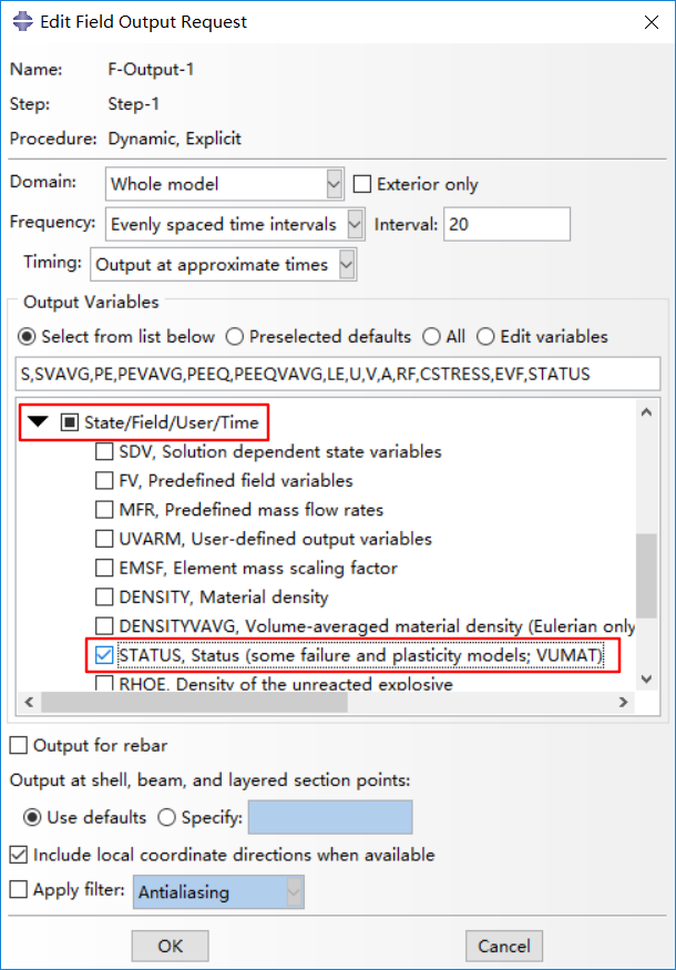
One point should be noticed that Status in field output should be ticked, so that elements with strain up to fracture strain will be deleted and you can obtain the fracture deformation you want, or the element will be scratched which would be annoying. The overall scalar stiffness degradation, SDEG, is also available for output.
The removal of a solid element takes place, by default, when maximum degradation is reached at any one integration point in abaqus/explicit, while only all of the section points at all the integration locations of an element reach maximum degradation in abaqus/standard.

Simulation results
A coupon is analyzed with dynamic explicit method and displacement control is adopted with one boundary fixed and the other boundary coupled to a reference point. Smooth step for amplitude with a displacement rate of 10mm in 5000 seconds.

As can be seen in the above figure, elements with equivalent plastic strain (PEEQ) reaching fracture strain are deleted in viewport. However, the fracture of specimen does not locate in the middle part, which puzzling me. I have checked the geometric information, the boundary and loading conditions, as well as the materials. Other methods like excluding coupling in interaction have also be tested and the same results are achieved.
Reference:
[1] Ling Li, Behavior of Steel Beam-to-Column Connections in Structural Progressive Collapse. [PhD thesis], Tongji University, 2014.
4 comments On Fracture analysis of a metal specimen
Just checking in to register my support. Your post is well put together Great job!
Never quit moving. Goals!
Cool
You make some solid statements.