I am using different spring elements for different directions in local coordinate system in ANSYS. At first, I could only add spring elements in global system even though I defined and activated local system, it just didn’t work. I searched on Google without satisfying results. Fortunately, I got this problem successfully solved with the help of a friend.
Problem description
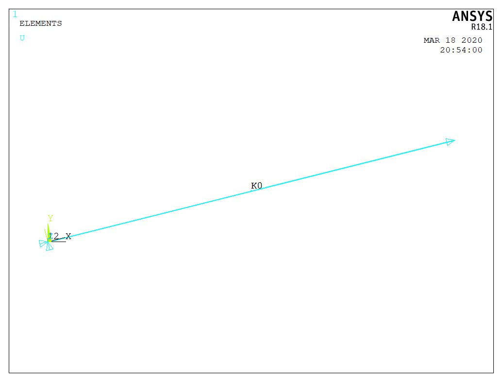
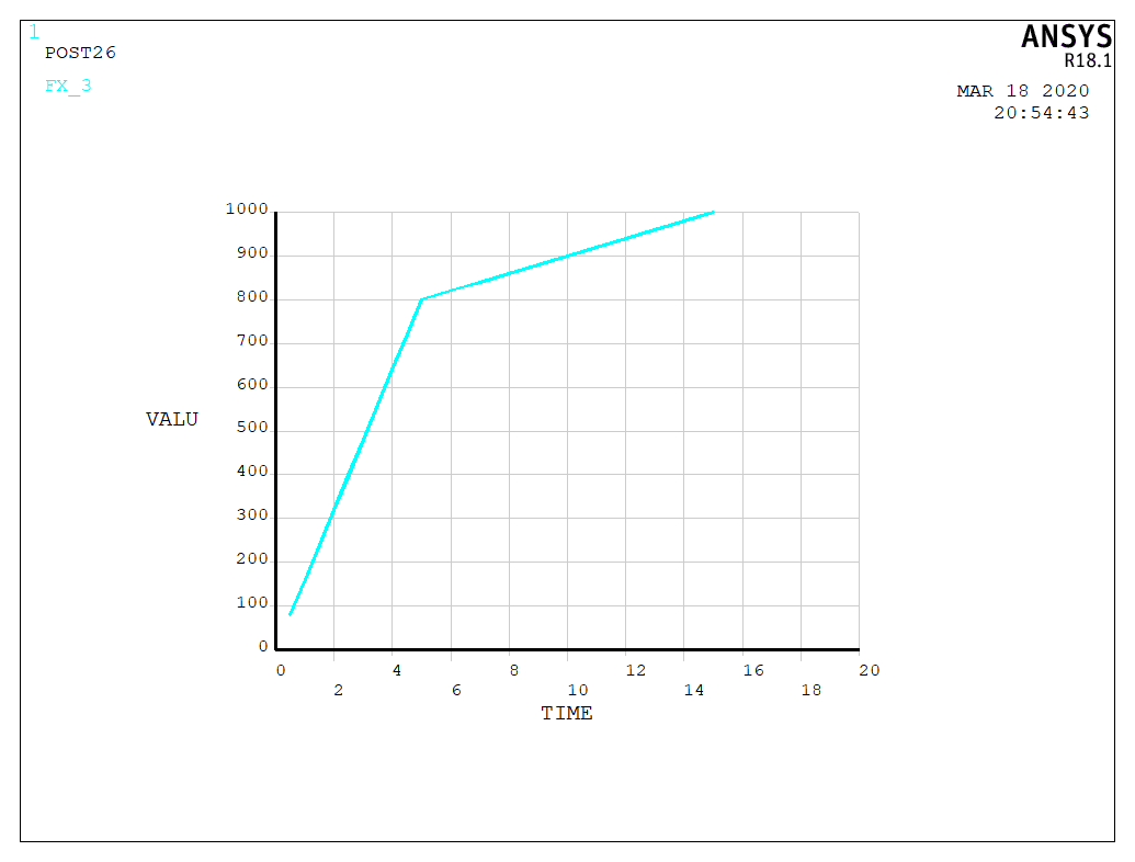
In this testing example, I used a rotated cantilever beam with two spring elements at x and y directions in local coordinate system. Bilinear curves are adopted for each spring element. For the axial spring, the two points at the force displacement curve is (5,800) and (10,900). To better illustrate the force-displacement relationship of the results, I used displacement control method with a maximum axial displacement 15.
It is worthwhile to mention, you will get warning message like Nodes I and J of element 1 ( COMBIN39 ) are not coincident. after running the codes below, and this is because the two nodes of spring element should be at the same position. I used different nodes just to show the rotation more clearly. The results are the same as those from the correct model.
APDL codes
/PREP7
len = 50
u0 = 15
! spring element
! axial
ET,1,COMBIN39
KEYOPT,1,1,0
KEYOPT,1,2,0
KEYOPT,1,3,0
KEYOPT,1,4,0
KEYOPT,1,6,0
R,1,0,0,5,800,10,900,
! transverse 1
ET,2,COMBIN39
KEYOPT,2,1,0
KEYOPT,2,2,0
KEYOPT,2,3,2
KEYOPT,2,4,0
KEYOPT,2,6,0
R,2,0,0,2,1500,8,3000,

! model
CSYS,0
CLOCAL,12,0,0,0,0,14.03624347,0,0
N,1,0,0,0
N,2,len,0,0
! rotate nodes
NROTAT,1,1,12
NROTAT,2,2,12
! spring element
CSYS,12
TYPE,1
REAL,1
E,1,2
CSYS,12
TYPE,2
REAL,2
E,1,2


/SOLU
! fixed end
CSYS,12
ALLSEL,ALL
NSEL,S,NODE,,1
CM,BC_FIX,NODE
! free end
CSYS,12
ALLSEL,ALL
NSEL,S,NODE,,2
CM,free_end,NODE
! apply fixed boundary condition
CSYS,12
ALLSEL,ALL
D,BC_FIX,ALL
! apply load
CSYS,12
ALLSEL,ALL
D,free_end, ,u0, , , ,UX, , , , ,
/SOLU
TIME,1
NSUBST,30,30,30
OUTRES,ALL,1
SOLVE

/POST1
RSYS,12
! force contour
PLESOL, F,X, 0,1.0
Result analysis
Looking at the reaction force (axial component) and the axial displacement of the free end, the force displacement curve is plotted as the following figure. We can see the two points (5,800) and (10,900) defined in the axial spring element are also in this figure. The slope in the hardening part remain the same, which is consistent with the assumption of the spring element. When checking the UY and FY, we can see the values are nearly zero.
Pay attention:
1. Node rotation: nodes associated with the spring elements have to be rotated before the analysis, or the spring will be defined in global coordinate system. No matter when you defined the node rotation, the directions of the forces applied on the rotated nodes will change to local axis.
2. Checking the force direction: if you define the node rotation after the load definition, refresh the window and then you can see the change of the force direction.
3. As explained in the ‘problem description’ part, the two nodes of the spring element should be at the same position and you will get warning message with the codes in this post. However, the results are correct.