2D frame
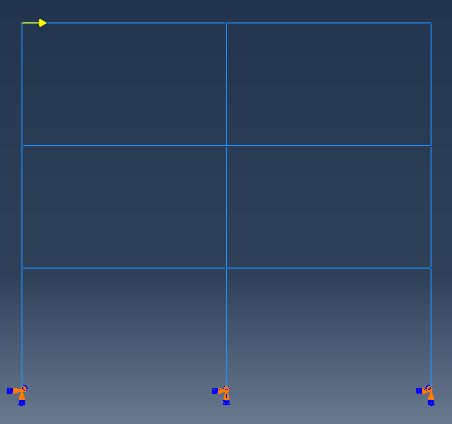
This is a plane steel frame with box sections subjected to a point load at one node figured as below.
An dynamic implicit analysis step was defined and the following lines were added at the end of input file.
**
*STEP
*MATRIX GENERATE, STIFFNESS, MASS, LOAD, Structural Damping,Viscous Damping
*MATRIX OUTPUT, STIFFNESS, MASS, LOAD, Structural Damping,Viscous Damping, FORMAT=COORDINATE
*END STEP
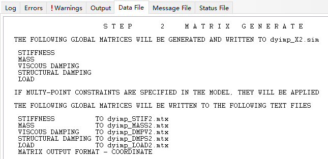
After the analysis completed, the Data file will be available and a screen shoot is provided below. The .mtx files are generated in the file folder, however, there is no dyimp_LOAD2.mtx file and this is a problem remained. I still don’t know how to fix it.
3D frame
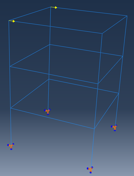
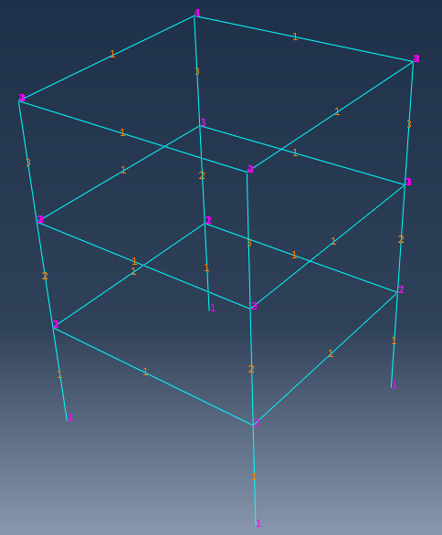
This is a 3D frame with rectangular sections subjected to two point loads. Firstly, the columns and beams were built, then they are assembled in ASSEMBLY section and finally I used the merge function and suppressed the original instances to form this frame. I also chose the Remove button to for the intersecting boundaries. The masses were applied on the nodes and as such the material density was set to zero. A dynamic implicit analysis case was defined and one element per member is used.
The same as the example of 2D frame, the codes were added to extract matrices from abaqus. The matrices were written in corresponding files.
However, I found the size of matrices are not consistent with the number of nodes. There are 16 nodes in this frame and the degree of freedom is 16*6=96, but the size of matrices are 144*144 and this is puzzling. To find out the reason of this, I re-extracted the matrices in coordinate form and defined a frequency step to output the element matrices. Also, I checked the numbers of nodes and elements in MESH section as follow.
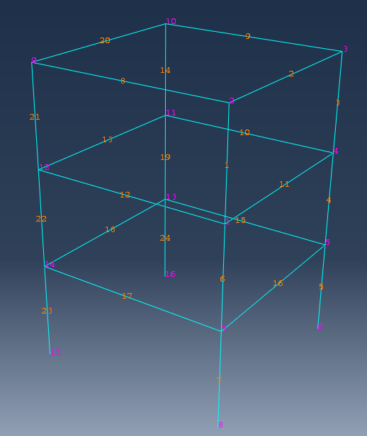
From the numbers in MESH section, there is no error in it. The matrices in Coordinate form show that both the row and column labels have negative values. The numbers are from -24 to +16 and the negative part is very confusing. The 24 negative numbers are the geometrical nodes (3*4*2) as I understand. However, why these degree of freedoms are not condensed is unknown, probably there is no defined restrains in INTERACTION section. The element matrices file shows there are totally 24 elements in the model and this result correspond with the structure.
From these results, it can be concluded that the negative numbers are from the assembling of global matrices. I guess this may result from the merge of beams and columns. Thus, I built another frame with Tie constrains on the nodes at the same position. The numbers in MESH section is illustrated as below.
It can be seen that every column has 4 nodes and every beam has 2, the sum is 40 nodes. In the matrices in coordinate form, the number of nodes is from 1 to 40, corresponding to total number of nodes. In the matrices in matrix input form, the maximum number of row and column labels is 96, equals to 16*6, meaning the nodes at the same position are condensed to one in global matrix because of the Tie constrains.
One more question, the matrix in matrix input form has more non-zero elements (1504) than matrix in coordinate form (800). This condition also exsists in the last model in this example and 2D frame example (12 nodes, 828 elements for coordinate form and 450 elements for matrix input form). In this example, there are 16 nodes after the condensation of degree of freedoms, so there will be 16*6=96 rows and lines, that is 96*96=9216 elements in the matrix. The number of non-zero elements in matrix in coordinate form except the diagonal part is 1504-96=1408. Half of the non-zero elements except the diagonal (1480/2=704) plus the the diagonal part (96) is the number of elements in matrix in matrix input form. The conclusion is that the matrix in matrix input form omits the symmetrical part of elements as you can fill in them according to the symmetry principle with the node numbers and degree of freedom numbers.
The six degree of freedoms of nodes 25, 29, 33, 37 (four button nodes) are set to be a very large value 1.0E+36 in stiffness matrix in matrix input form, and the value of row and column labels 1~6, 25~30, 49~54, 73~78 are also 1.0E+36 in stiffness matrix in coordinate form. The assembling of global is not according to the sequence of node numbers.
Up to now, I haven’t found any explanations in official support documents about the negative node number. If you want to extract the matrices from abaqus and use them in other software, you’d better establish the model in the second way in this example I think.
Updated 2018/8/24
Exporting the load vectors
Section 10.3.1 in Abaqus Analysis User’s Guide
All types of loads can be applied in the load cases for a matrix generation step. Real and imaginary parts of the load vectors will be generated for the complex loads. Any loads that are defined in a matrix generation step will not be used in subsequent general analysis steps (unless they are respecified).
So, in the matrix generation step, we need to define the load again and the load matrix can be exported to .mtx file. The codes for exporting matrices in input file is described below.
*STEP
*MATRIX GENERATE, STIFFNESS, MASS, LOAD, Structural Damping,Viscous Damping
*MATRIX OUTPUT, STIFFNESS, MASS, LOAD, Structural Damping,Viscous Damping, FORMAT=COORDINATE
** LOADS
**
** Name: Load-1 Type: Concentrated force
*Cload, amplitude=Amp-1
_PickedSet79, 1, 100.
**
**
*END STEP
The vector in LOAD.mxt file is listed as
** Assembled nodal loads
*CLOAD, REAL
19 9.999999999999999e-35
67 9.999999999999999e-35
Updated 2019/01/06
Negative values in row and column labels in matrix
I found the reason for negative values in row and column labels in matrix yesterday and tried to check this out this morning. The reason for this phenomenon lies on the method of merge. Three methods, geometry, mesh and both, are included in ABAQUS, as shown below.
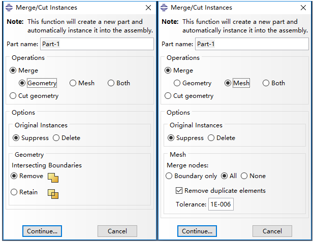
In the first method, Geometry, only the intersecting boundaries are removed and the duplicate nodes are also removed. In the second method, Mesh, the duplicated elements as well as the nodes can be removed. A prompt message will emerge “The nodes highlighted in magenta will be merged. OK to merge?” The matrix exacted by this method do not contain row and column labels with negative values.
Since I cannot find the original model and codes, I tried to merge the model with the two methods and found the matrix of them do not contain negative values either. The negative value I got before might be the result of forgetting to choose Remove intersecting boundaries.
To sum up, if you do not want to have negative rows and columns, you can use INTERACTION (such as tie, MPC) to deal with the nodes of elements or you can merge with Geometry or Mesh and remember to choose to remove the duplicate nodes. When you merge with Geometry and retain the intersecting boundaries, negative values will be generated in the matrix.
6 comments On Examples of extracting matrices from ABAQUS
Hi Dorothy,
I think this post goes in the direction of my problem.
I have created a beam with a fixed restraint and deposited steel as material model. Works great. For a student research project I need the mass and stiffness matrices for a body that consists of a hyperelastic model. The instructions for exporting the matrices also work for this.
The only problem is that at the beginning a number of entries is zero. As an example: A beam consists of 53 nodes, so I get in the TXT file for the mass matrix in the format(coordinate) 424 entries, of which they are the first 106 entries zero, so
1 1 0
2 2 0
.
.
.
106 106 0
After that, the entries are shifting from zero, so in the end there are 318 entries different from zero (53 nodes a 6 degrees of freedom = 318 entries). So that the entries subsequently look as follows:
107 107 x
.
.
.
424 424 y
My question now is, what do the first 106 entries in which there is a zero mean? The mass and stiffness matrix is to be read into MatLab afterwards. Only zeros on the main diagonal are not advantageous, if the matrix has to be inverted. As element type currently C3D4H is used.
I hope someone has a tip. Thanks a lot !
Greetings
Zemos
Hi Nico,
Sorry about late reply, I was focusing on my qualifying exams. I did not use C3D4H element before and am not sure what are the zeros. I would suggest to output the matrices in matrix input format
FORMAT=MATRIX INPUT, and then you will know where the zeros locate, at which node and which dof. Hope this helps.Hi Nico,
i have the same problem with my results. Did you found a solution to that ?
Best, Sebastian
Hi, Dorothy. Thanks for your job. Buut do you know how to export the Jacobian (ddsdde) of the specified integration point? I may need to have a check of the ddsdde.
Regards, Daniel
Hi Dorothy,
Your post helped me a lot. but, I still got negative nodes in mtx.file. my model was a simple cube under vertical load, there is no contact happening here. is there a reason why I got negative nodes? do you know have to fix this one? looking forward to your reply.
Best, Aaron
Hi Aaron,
I got negative values in the matrix probably because I forgot to choose Remove intersecting boundaries. But I cannot verify this since I lost the original model and script.
Which merge method did you use when establish your model? You may try to rebuild the model to see if there are any negative values.
Hope this helps.
Best,
Dorothy